Electrical Power System
An EPS is divided into power generation and processing hardware, an energy storage mechanism, output power regulation, and data collection instrumentation. The three power budgeting categories for an EPS are power generation, power distribution, and power consumption, also known as power conversion and regulation. All power budgeting categories exhibit losses to be accounted for when developing a power profile for the spacecraft, and power consumption values differ per software mode. For ABEX, we have a solar array for power generation with two Maximum Power Point Trackers in the EPS, a Battery Management System per battery pack, DC/DC conversion boards to supply the spacecraft with 3.3 V, 5 V and 12 V power rails, and data organization hardware to provide the Command & Data Handling (C&DH) subsystem with detailed information about the health and operation of the EPS.
|
TPM |
Rationale |
Units |
|---|---|---|
|
Average Power Supplied by EPS at Output Voltage Rails |
The EPS must meet the average power requirements of the CubeSat. |
W |
|
EPS Peak Power |
The EPS electronics should handle or meet/exceed the peak power draw of each CubeSat Subsystem. |
W |
|
EPS Battery Capacity Required Before & During Deployment |
The capacity of the batteries must be sufficient during the deployment stage of the CubeSat. |
Wh |
|
EPS Battery Capacity Required Post Deployment Operation |
The capacity of the batteries must be sufficient to power the CubeSat during solar power interruptions or high-power demand that exceeds the solar panels’ power. |
Wh |
|
Number of Battery Packs and BMS Channels |
The batteries are split into at least two packs, each with its own Battery Management System, to allow for battery power even if one pack fails. The failure of one battery pack should not interrupt the operation of the other battery packs. |
N/A |
|
Number of MPPTs |
The solar cells are split between at least two Maximum Point Power Trackers to allow for energy harvesting in the event one MPPT fails or in the event of solar cell degradation or loss. |
N/A |
|
EPS 12V Output Current |
The EPS rated output current must be capable of supplying the peak power of the loads on the 12V rail using DC-DC Converters. |
amp |
|
EPS 5V Output Current |
The EPS rated output current must be capable of supplying the peak power of the loads on the 5V rail using DC-DC Converters. |
amp |
|
EPS 3.3V Output Current |
The EPS rated output current must be capable of supplying the peak power of the loads on the 3.3V rail using DC-DC Converters. |
amp |
|
EPS Umbilical Cord Charging Rate |
The umbilical cord must be capable of charging the battery packs in the time allotted during launch vehicle loading. |
Wh |
|
Ground Power Delivery |
The umbilical cord must supply direct power to DC-DC converters to maintain the operation of the CubeSat when the kill and deployment switches disconnect battery power and solar panels power. |
W |
|
EPS Mass |
The EPS must maintain minimum mass for a 74-W/TBD average and 140–W/TBD peak power at its output. The EPS might include 10-15/TBD battery cells, 2 MPPTs, 3 channels BMS, 3-6/TBD DC-DC converters, interface circuits, and an umbilical cord interface. |
g |
|
Number of EPS PCBs |
The EPS must maintain minimum mass for a 74-W/TBD average and 140–W/TBD peak power at its output. The EPS might include 10-15/TBD battery cells, 2 MPPTs, 3 channels BMS, 3-6/TBD DC-DC converters, interface circuits, and an umbilical cord interface. |
N/A |
This content is coming soon!
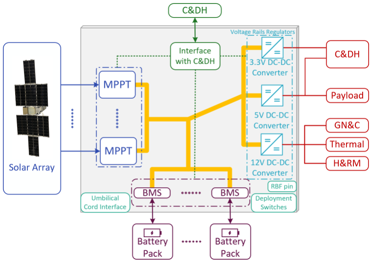
The high-level conceptual block diagram of the Electrical Power System (EPS) is illustrated in the Figure. Each Maximum Power Point Tracking (MPPT) battery charging controller provides pulse-modulated control signals to its corresponding MPPT power converter (e.g., four-switch buck-boost DC-DC converter) in order to maximize the power extracted from the corresponding photovoltaic (PV) solar panel (or from a group of PV cells/strings in a solar panel). At least two MPPT channels are used, allowing for higher harvested power when there is mismatched, partially shaded, and/or surface scratched solar cells, preventing single failure points. The current/power generated at the output of all MPPT converters is summed and connected to both the inputs of the DC-DC power converters (voltage regulators) of the voltage rails (e.gs. 3.3 V, 5 V, and 12V) and the battery pack(s). The power converters/voltage regulators of the voltage rails supply regulated voltages to the CubeSat’s other subsystem loads (e.g. C&DH, Payload, GN&C, Thermal, and H&RM). When the power generated at the output of the MPPTs (from the PV solar panels) is larger than what the subsystem loads need (are drawing/consuming) under a given operation state of the CubeSat, the rest of the power that is not being used by the subsystem load is used to charge the battery pack(s). When the power needed by subsystem loads is higher than the power available at the output the MPPTs (e.g. under occasional peak power demands, during deployment stage, and/or when there is a loss or a reduction in the available PV solar energy), the rest of the needed power by the subsystem loads will be supplied by the battery pack(s). The number of needed battery cells can be distributed between multiple battery packs, each with its own Battery Management System (BMS), instead of a one-battery pack with one BMS. This provides redundancy in case a battery cell, pack, or BMS failed (to prevent single failure points). For example, 15 battery cells can be divided between 3 battery packs (each with its own BMS), with each battery pack consisting of 5 battery cells connected in series (5S configuration). Then the three battery packs can be connected in parallel. If a battery pack has a faulty or aged cell, the BMS is able to disconnect this battery pack and the result of the battery packs should be able to continue normal operation. The BMS will also perform functions such as battery cells balancing and protection during charging and discharging and data reporting to C&DH such as battery pack State-Of-Charge (SOC), temperature, current, and voltage. Of course, there is tradeoff between mass, volume, and cost from one side and redundancy and risk reduction from another side when determining the number of battery packs and the number of MPPTs.
The sizing of the solar panels and battery packs should be such that they meet the power demands of the CubeSat subsystems/loads under all operation scenarios. Moreover, the sizing of the battery pack(s) should be such that it is sufficient to meet the power demand during the deployment stage before the EPS is able to start harvesting solar energy after the deployment of the solar panels.
The EPS design should accommodate two deployment switches and at least one Remove Before Flight (RBF) pin or kill switch. In the actuated state, the CubeSat deployment switches shall electrically disconnect the power system from the powered functions. The RBF pin shall cut all power to the satellite once it is inserted into the satellite and shall be removed from the CubeSat after integration in the dispenser. The EPS design should allow the umbilical cord to charge the battery and power the subsystem loads from an external power source in addition to providing the ability to update and program the computer software.
The in-house developed EPS option might include multiple PCBs. The PCBs, except for the battery cells interface PCB with BMS, will be located inside the avionics box. One or more battery boxes (for one or more battery packs) each include a mounting PCB which also has interface connectors to connect to the BMS PCB located inside the avionics box.